
The Rankine cycle closely describes the process by which steam engines commonly found in thermal power generation plants harness the thermal energy of a fuel or other heat source to generate electricity. Possible heat sources include combustion of fossil fuels such as coal, natural gas, and oil, use of mined resources for nuclear fission, renewable fuels like biomass and ethanol, and energy capture of natural sources such as concentrated solar power and geothermal energy. Common heat sinks include ambient air above or around a facility and bodies of water such as rivers, ponds, and oceans.
The ability of a Rankine engine to harness energy depends on the relative temperature difference between the heat source and heat sink. The greater the differential, the more mechanical power can be efficiently extracted out of heat energy, as per Carnot's theorem.
The efficiency of the Rankine cycle is limited by the high heat of vaporization of the working fluid. Unless the pressure and temperature reach supercritical levels in the boiler, the temperature range over which the cycle can operate is quite small. As of 2022, most supercritical power plants adopt a steam inlet pressure of 24.1 MPa and inlet temperature between 538°C and 566°C, which results in plant efficiency of 40%. However, if pressure is further increased to 31 MPa the power plant is referred to as ultra-supercritical, and one can increase the steam inlet temperature to 600°C, thus achieving a thermal efficiency of 42%.[1] This low steam turbine entry temperature (compared to a gas turbine) is why the Rankine (steam) cycle is often used as a bottoming [clarification needed] cycle to recover otherwise rejected heat in combined-cycle gas turbine power stations. The idea is that very hot combustion products are first expanded in a gas turbine, and then the exhaust gases, which are still relatively hot, are used as a heat source for the Rankine cycle, thus reducing the temperature difference between the heat source and the working fluid and therefore reducing the amount of entropy generated by irreversibility.
Rankine engines generally operate in a closed loop in which the working fluid is reused. The water vapor with condensed droplets often seen billowing from power stations is created by the cooling systems (not directly from the closed-loop Rankine power cycle). This "exhaust" heat is represented by the "Qout" flowing out of the lower side of the cycle shown in the T–s diagram below. Cooling towers operate as large heat exchangers by absorbing the latent heat of vaporization of the working fluid and simultaneously evaporating cooling water to the atmosphere.
While many substances can be used as the working fluid, water is usually chosen for its simple chemistry, relative abundance, low cost, and thermodynamic properties. By condensing the working steam vapor to a liquid, the pressure at the turbine outlet is lowered, and the energy required by the feed pump consumes only 1% to 3% of the turbine output power. These factors contribute to a higher efficiency for the cycle. The benefit of this is offset by the low temperatures of steam admitted to the turbine(s). Gas turbines, for instance, have turbine entry temperatures approaching 1500 °C. However, the thermal efficiencies of actual large steam power stations and large modern gas turbine stations are similar.
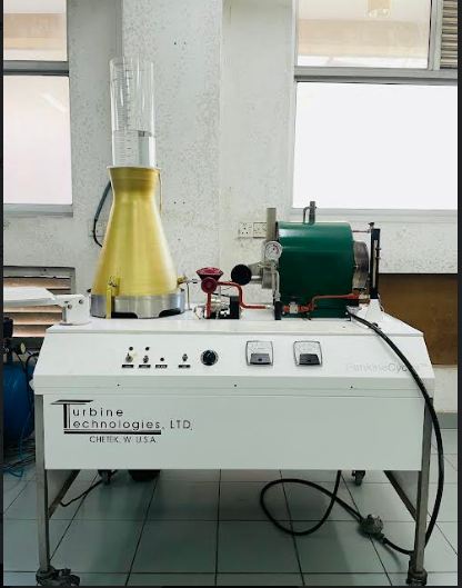
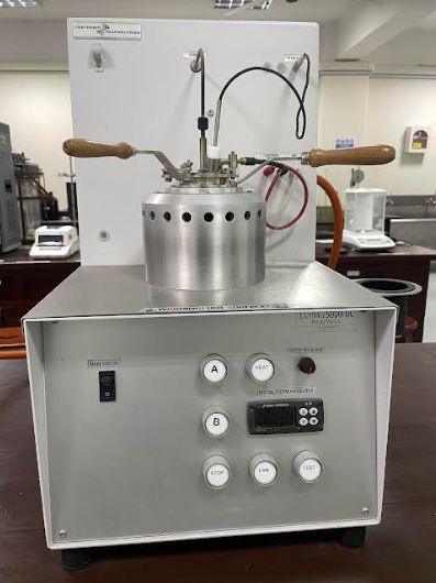
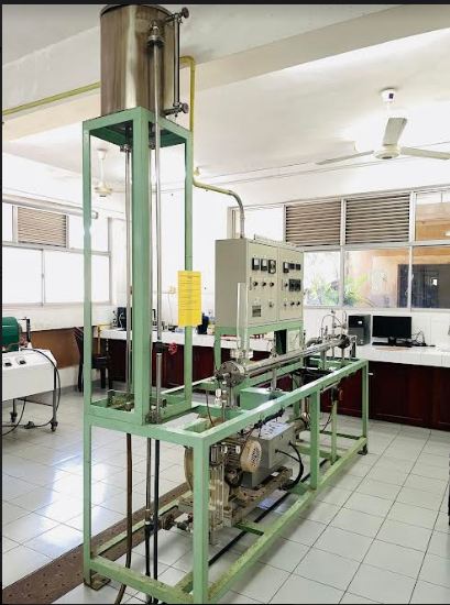
Rankine cycler
University of Moratuwa
-
Faculty: Faculty of Engineering
-
Department: Department of Chemical and Process Engineering
-
Laboratory : Transport Phenomena
Product Category/ Test Name (Matrix):
Test and Measurement Equipment
Sub Category:
Keywords:
Service Charge (Rs) - 


.jpg)
.jpg)


.jpg)


.jpg)

.jpg)
.jpg)
.jpg)
1.jpg)
.jpg)
.jpg)
.jpg)


.jpg)
.jpg)
.jpg)
.jpg)
.jpg)
.jpg)
.jpg)
.jpg)
.jpg)
.jpg)
.jpg)


.jpg)


.jpg)
.jpg)


.jpg)


.jpg)


1.jpg)


1.jpg)


.jpg)

.jpg)


.jpg)


.jpg)


.jpg)
.jpg)

.jpg)


3.jpg)


_FN_500P.jpg)


.jpg)
.jpg)
.jpg)


1.jpg)


.jpg)
.jpg)